Monday, April 21, 2014

​I had hopes that it would not be a challenging work, but it was not as easy as I thought. First things first, I didn't invent this pan/tilt mechanism, the one comes with Pixy is a similar solution. So if there is credit it goes to the project team. I got the inspiration (!) from them.

The old friend HDPE comes to the stage again. Why do I use this stuff for everything, because;

I have it,
It's durable, a little flexible but not brittle,
It's machineable, drillable, sandable and can be filed like soft metals, and can be cut with any small teeth saw.
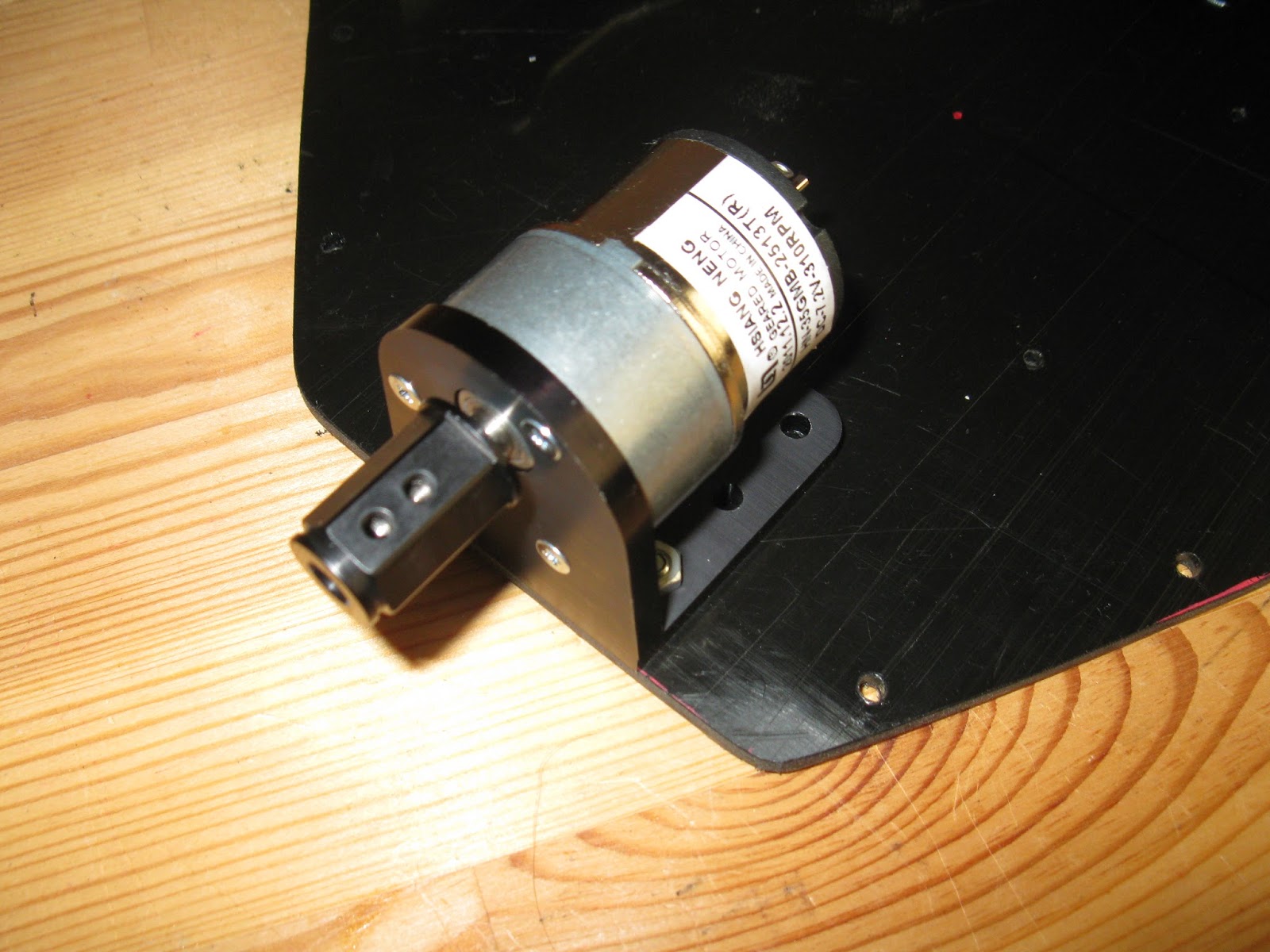
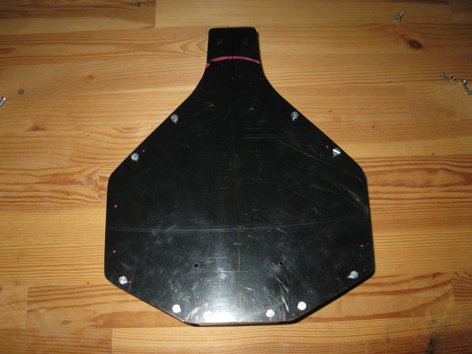
and it looks good. ​​Below are the stages for creating the pan/tilt mechanism. Pan servo is fastened with screws, but tilt servo is kept only with the bracket (painted in black, later) and there is a small trick to keep it in place. I made a small groove on the plate and filed one side of the mount of servo to fit in that groove, so that it doesn't move back and forth.


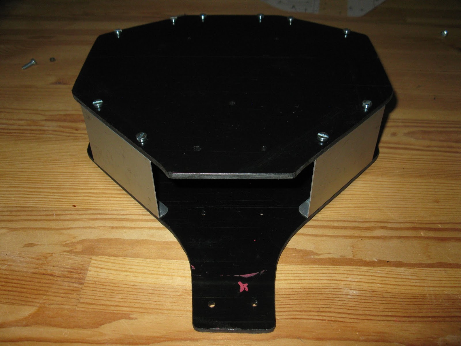
And, the final product put together,


Sunday, April 6, 2014

After months of waiting, I received my Pixi. I mentioned before, it was one of the Kickstarter projects that I backed. The guys from Charmed Labs and Carnegie Mellon are behind it. It's a vision sensor that can quickly be taught new objects, and it can be connected directly to Arduino. Which suits me nicely because for this project I'm using another Arduino compatible board DigiX. It's also from Kickstarter but another story.

Here are the first pictures of the product, mounting brackets fastened.


It processes images at a frame rate of 50 Hz and support multiple interfaces: UART serial, SPI, I2C, digital out, or analog out. I must say that from my point of view, the result of the project was the best one so far coming from Kickstarter. There was also an optional purposefully built pan/tilt kit but I thought that I could make it by myself by using servos out of the house-stock.

Wednesday, March 12, 2014

I've made the piece that I mentioned in my previous post. It's a simple U shape aluminum to connect the claw to the pan/tilt bracket.


Then, I mounted the claw on a test platform to see how it works. In the video you'll see that a servo tester in automatic mode tilting and opening the claw.

Will this be able to lift up a softdrink can ? Not sure yet, we'll see.


and, here is the video,


Monday, February 3, 2014

It's been a time since my last post. Business and other stuff as expected.
Thank you guys for your comments and feedback.

In the meantime I purchased some parts for my robot. I'm not sure yet how I can make use of them in the end but we'll see.

One of the items that I bought is Sparkfun Robotic Claw MK II with its Pan/Tilt Bracket.
The claw is made from metal and has a spring clutch, I hope it will save the servo from ruining.
The more complex looking claw is surprisingly cheaper than the bracket, but the bracket comes with its servo. Even though it says the bracket is made especially for the claw there is no easy way to put them together. The assembly instructions are really poor and the proposed method doesn't fit my liking so I decide to make a U shape piece as an adapter between to screw them together.

Here you can see the pictures, I just installed the servos;


Friday, October 18, 2013

So far I've spent much of the time on mechanics rather than the electronics. But, I'm not in a hurry and try to get the joy of doing things slow but steady. The chassis is almost done, I'll add some handles and maybe some protective rubber caps, just in case it decides to run away and hit somewhere.


Friday, October 11, 2013

I have two stock motors from Parallax, they are 7.2 volt and 310 rpm. My concern is that they are a little bit faster than I want them to be. I see that many people replace them, anyway. I'd prefer torque over speed, and I think a higher gear ratio will make it more stable. BTW, I'd like to thank Erco for finding the lower rpm replacement motors on Ebay. I guess I'll use the similar ones which are 70 rpms but 12 volt. I don't know yet if my 6 cells 7.2 volt NIMh battery pack would provide enough juice for them.


Monday, October 7, 2013

After a few busy weeks, found some time to work on my robot again. I brushed the aluminum tail that I cut from 2 mm sheet. It looked straightforward in the video I mentioned previously, but believe me it is a long and laborious process. It took me almost half an hour just to brush one side with 180 grade sand paper. The pictures were taken ten minutes apart.


Wednesday, October 2, 2013

The tail assembly would become sturdier if there is a support from the buttom upward. And here is he solution. It's the same kind of aluminum, 2 mm thick. Cut and filed by manual tools.


I have nothing but an old vise to use for bending. But the trick is; first make a groove around (0.5 mm) on the plate where you want to bend with a dremel cutting disc, and then bend it slowly. Before bending, I made some brushing with 240 grit sand paper. I'm very happy with the result, it's just great, isn't it?


Thursday, September 26, 2013

Voila! the marriage! Car manufacturers call this moment as a "marriage" when the upper body meets with the lower part. This is the first time the full chassis come together.


Monday, September 23, 2013

Side panels are almost ready, I think I'm going to use the stock motor mounts that comes with Parallax motors. I want my robot a little high on the ground then maybe it can go outdoor and hairy carpets won't be a problem. For that, I designed the height as 50 mm, plenty enough to put the battery, motor controllers and obviously the motors in the chassis.


Wednesday, September 18, 2013

Now, It's time to focus on Stingray's tale. Since I use Parallax caster wheel I need to make a mount for the wheel which attaches to the chassis. Pictures tell much more than words,


I cut this piece from an aluminum sheet that is 2 mm thick,


At the final stage, after drilling and happy with the result, I will give the brushed aluminum effect manually, this is the how to video on youtube.

Saturday, September 14, 2013

And the side panels, as I said these are made out of aluminum,


I also prepared a template for the bolt holes to make sure that each side panel has the exact same drill pattern,


I had some concerns that the aluminum profile was too thin (1 mm) but having had no alternative after some experiment it turned out to be fairly sturdy, especially after the bolts are done.